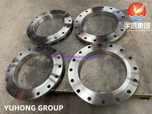
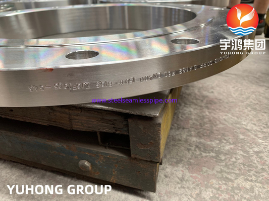
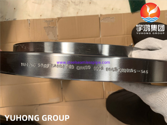
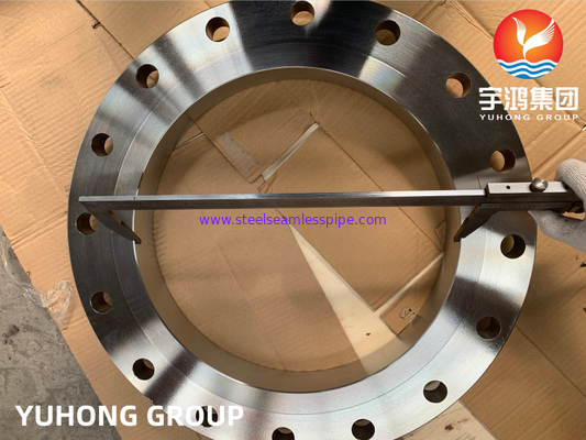
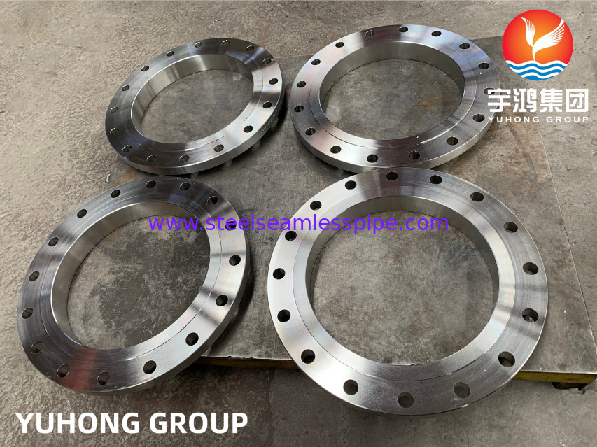
Duplex Stainless Steel Flange ASTM A182 F60 Welding Neck Forged Rasied Face Flanges
Flangs are widely used due to their high pressure bearing feature and high strength in transmission service. ASTM A182 F60 chemical composition contains carbon, manganese, phosphorus, sulfur, and silicon. The ASTM A182 F60 material also contains 3-4 % molybdenum. ASME B16.5 Duplex F60 Flanges are available in various sizes and shapes and range between 0.5 inches to 24 inches in diameter. F60 Flanges have different pressure classes and their capacity is expressed between 5K to 63K in the JIS system.
For maximum grip on pipe A182, F60 Weld neck flanges are used since they have a welded neck which helps in tightening the grip. ASTM A182 F60 equivalent is easy to weld and has high fatigue strength. The melting point of F60 duplex stainless steel flanges is 1420 degrees C. These ASTM A182 grades F60 flanges also provide you with a tensile strength of 515 MPa and yield strength of 415 MPa. ASTM A182 Duplex F60 Flanges are passed through various tests before the final product is delivered. These tests include radiology, flaring, flattening, visual, macro and micro. F60 duplex stainless steel Slip-on Flange is one of the high-demand products used in industries such as petrochemical, gas processing, offshore oil drilling, power generations, condensers, and pulp and paper industries.The material composition of ASTM A182 F60 flanges contains 3-3.5% molybdenum. This level has different pressure levels, ranging from CLASS 150 to 2500 LBS.
The melting point of the flange material is 1420 degrees Celsius. This allows the flange to operate at high temperatures. There is a welding neck on the A182 F60 welding neck flange, which can hold the pipe to the greatest extent during the welding process. The material has high fatigue strength and is easy to weld. Gaskets are used to fasten flanges and pipes together during welding. We can provide f60 duplex stainless steel sliding flanges and other products. Please feel free to contact us for more information and prices.
Full Specification for Weld Neck Flange:
1. Standards:
(1) American Standard
ASME/ANSI B 16.5
(2) German Standard
DIN2641, DIN2642
(3) British Standard
BS 1560, BS 4504
(4) Australian & Japanese Standard
JIS B2220 / KS B1503, AS2129,
2. Material:
F60 (F50, F51, F52, F53, F54, F55, F57, F59, F60, F61, F69, etc.)
| Ferritic-Austenitic Stainless Steels |
| |
|
Composition, % |
|
Grade/
Identification
Symbol
|
UNS
Designation |
Carbon |
Manganese |
Phosphorus |
Sulfur |
Silicon |
Nickel |
Chromium |
Molybdenum |
Columbium |
Titanium |
Other
Elements |
| F 50 |
S31200 |
0.030 |
2.00 |
0.045 |
0.030 |
1.00 |
5.5-6.5 |
24.0-26.0 |
1.20-2.00 |
- |
- |
N 0.14-0.20 |
| F 51 |
S31803 |
0.030 |
2.00 |
0.030 |
0.020 |
1.00 |
4.5–6.5 |
21.0–23.0 |
2.5–3.5 |
- |
- |
N 0.08–0.20 |
| F 69 |
S32101 |
0.040 |
4.00–6.00 |
0.040 |
0.030 |
1.00 |
1.35–1.70 |
21.0–22.0 |
0.10–0.80 |
- |
- |
N 0.20–0.25
Cu 0.10–0.80
|
| F 52 |
S32950 |
0.030 |
2.00 |
0.035 |
0.010 |
0.60 |
3.5–5.2 |
26.0–29.0 |
1.00–2.50 |
- |
- |
N 0.15–0.35 |
| F 53 |
S32750 |
0.030 |
1.20 |
0.035 |
0.020 |
0.80 |
6.0-8.0 |
24.0--26.0 |
3.0-5.0 |
- |
- |
N 0.024-0.32 Cu 0.50 |
| F 54 |
S39274 |
0.030 |
1.00 |
0.030 |
0.020 |
0.80 |
6.0-8,0 |
24.0-26.0 |
2.5-3.5 |
- |
- |
N 0.24-0.32 Cu 0.20-0.80 |
| F55 |
S32760 |
0.030 |
1.00 |
0.030 |
0.010 |
1.00 |
6.0-8.0 |
24.0-26.0 |
3.0-4.0 |
- |
- |
N 0.20-0.30 Cu 0.50-1.00 |
| F 57 |
S39277 |
0.025 |
0.80 |
0.025 |
0.002 |
0.80 |
6.5-8.0 |
24.0-26.0 |
3.0-4.0 |
- |
- |
Cu1.20-2.00 NW 0.80-1.20 |
| F 59 |
S32520 |
0.030 |
1.50 |
0.035 |
0.020 |
0.80 |
5.5-8.0 |
24.0-26.0 |
3.0-5.0 |
- |
- |
N 020-0.35 Cu 0.50-3.00 |
| F 60 |
S32205 |
0.030 |
2.00 |
0.030 |
0.020 |
1.00 |
4.5-6.5 |
22.0-23.0 |
3.0-3.5 |
- |
- |
N 0.14-0.20 |
| F 61 |
S32550 |
0.040 |
1.50 |
0.040 |
0.030 |
1.00 |
4.5-6.5 |
24.0-27.0 |
2.9-3.9 |
- |
- |
Cu 1.50-2.50 N 0.10-0.25 |
3. Pressure Ratings:
PN2.5, PN6, PN10, PN16, PN25, PN40, PN64, PN80, PN100, PN250, PN320, PN400
150LB, 300LB, 400LB, 600LB, 900LB, 1500LB, 2500LB;
4. Size Range:
1/2" ~ 24" (DN15 ~ DN600)
Dimensions and weights of Class 150 Flange
|
SIZE
|
FLANGE
|
BARREL
|
BOLTING
|
Raised
Face Dia.
R
|
LENGTH
L
|
WEIGHT
|
|
Nom
|
Unit
|
Bore
B
|
OD
O
|
Thk
T
|
OD
D
|
No. OF
Holes
|
Hole
Size
|
Bolt
Circle
C
|
POUND
KILO
|
|
1/2
|
mm
inches
|
12,7
0,50
|
88,9
3,50
|
11,2
0,44
|
31,8
1,25
|
4
|
15,7
0,62
|
60,5
2,38
|
34,9
1,38
|
228,6
9,00
|
3
1,36
|
|
3/4
|
mm
inches
|
19,1
0,75
|
98,6
3,88
|
12,7
0,50
|
41,1
1,62
|
4
|
15,7
0,62
|
69,9
2,75
|
42,9
1,69
|
228,6
9,00
|
5
2,27
|
|
1
|
mm
inches
|
25,4
1,00
|
108,0
4,25
|
14,2
0,56
|
50,8
2,00
|
4
|
15,7
0,62
|
79,2
3,12
|
50,8
2,00
|
228,6
9,00
|
7
3,17
|
|
1 1/4
|
mm
inches
|
31,8
1,25
|
117,3
4,62
|
15,7
0,62
|
60,5
2,38
|
4
|
15,7
0,62
|
88,9
3,50
|
63,5
2,50
|
228,6
9,00
|
10
4,54
|
|
1 1/2
|
mm
inches
|
38,1
1,50
|
127,0
5,00
|
15,5
0,69
|
66,5
2,62
|
4
|
15,7
0,62
|
98,6
3,88
|
73,0
2,88
|
228,6
9,00
|
12
5,44
|
|
2
|
mm
inches
|
50,8
2,00
|
152,4
6,00
|
19,1
0,75
|
82,6
3,25
|
4
|
19,1
0,75
|
120,7
4,75
|
92,1
3,63
|
228,6
9,00
|
15
6,81
|
|
2 1/2
|
mm
inches
|
63,5
2,50
|
177,8
7,00
|
22,4
0,88
|
95,3
3,75
|
4
|
19,1
0,75
|
139,7
5,50
|
104,8
4,13
|
228,6
9,00
|
22
9,98
|
|
3
|
mm
inches
|
76,2
3,00
|
190,5
7,50
|
23,9
0,94
|
108,0
4,25
|
4
|
19,1
0,75
|
152,4
6,00
|
127,0
5,00
|
228,6
9,00
|
25
11,35
|
|
3 1/2
|
mm
inches
|
88,9
3,50
|
215,9
8,50
|
23,9
0,94
|
124,0
4,88
|
8
|
19,1
0,75
|
177,8
7,00
|
139,7
5,50
|
228,6
9,00
|
32
14,52
|
|
4
|
mm
inches
|
101,6
4,00
|
228,6
9,00
|
23,9
0,94
|
139,7
5,50
|
8
|
19,1
0,75
|
190,5
7,50
|
157,2
6,19
|
304,8
12,00
|
47
21,33
|
|
5
|
mm
inches
|
127,0
5,00
|
254,0
10,00
|
23,9
0,94
|
165,1
6,50
|
8
|
22,4
0,88
|
215,9
8,50
|
185,7
7,31
|
304,8
12,00
|
57
25,87
|
|
6
|
mm
inches
|
152,4
6,00
|
279,4
11,00
|
25,4
1,00
|
196,9
7,75
|
8
|
22,4
0,88
|
241,3
9,50
|
215,9
8,50
|
304,8
12,00
|
75
34,05
|
|
8
|
mm
inches
|
203,2
8,00
|
342,9
13,50
|
29,4
1,12
|
247,7
9,75
|
8
|
22,4
0,88
|
298,5
11,75
|
269,9
10,63
|
304,8
12,00
|
102
46,30
|
|
10
|
mm
inches
|
254,0
10,00
|
406,4
16,00
|
30,2
1,19
|
304,8
12,00
|
12
|
25,4
1,00
|
362,0
14,25
|
323,9
12,75
|
304,8
12,00
|
143
64,92
|
|
12
|
mm
inches
|
304,8
12,00
|
482,6
19,00
|
31,8
1,25
|
365,3
14,38
|
12
|
25,4
1,00
|
431,8
17,00
|
381,0
15,00
|
304,8
12,00
|
205
93,07
|
|
14
|
mm
inches
|
355,6
14,00
|
133,4
31,00
|
35,1
1,38
|
406,4
16,00
|
12
|
28,4
1,12
|
476,3
18,75
|
412,8
16,25
|
304,8
12,00
|
211
95,79
|
|
16
|
mm
inches
|
406,4
16,00
|
596,9
23,50
|
36,6
1,44
|
457,2
18,00
|
16
|
28,4
1,12
|
539,8
21,25
|
469,9
18,50
|
304,8
12,00
|
246
111,68
|
|
18
|
mm
inches
|
457,2
18,00
|
635,0
25,00
|
3,96
1,56
|
508,0
20,00
|
16
|
31,8
1,25
|
577,9
22,75
|
533,4
21,00
|
304,8
12,00
|
270
122,.58
|
|
20
|
mm
inches
|
508,0
20,00
|
698,5
25,50
|
42,9
1,69
|
558,8
22,00
|
20
|
31,8
1,25
|
635,0
25,00
|
584,2
23,00
|
304,8
12,00
|
311
141,19
|
|
24
|
mm
inches
|
609,6
24,00
|
812,8
32,00
|
4,78
1,88
|
666,8
26,25
|
20
|
35,1
1,38
|
749,3
29,50
|
692,2
27,25
|
304,8
12,00
|
423
192,04
|
The end face type of flange A182 F60 can also be different, such as flat, raised and ring joint flanges. Flat flanges have flat surfaces, which allows them to be used in narrow spaces, where raised flanges have many surfaces for bolting and welding connections. The ring flange is divided into two halves, which are welded to different pipe ends, and they are combined by welding to obtain the maximum seal.
Flanges are part of the piping system and are used inside or outside the pipeline. Many types of flanged pipes are commonly used in piping systems. Flanges are like bridges, connecting pipes or fittings, making the pipe a complete system. Flange is an indispensable part of connecting pipes.
Pipe fittings are parts used to install or repair pipelines or pipeline systems that transport liquid, gas, and solid materials. This work includes selecting and preparing pipes or pipes, connecting them together in various ways, and locating and fixing vulnerabilities.


 Your message must be between 20-3,000 characters!