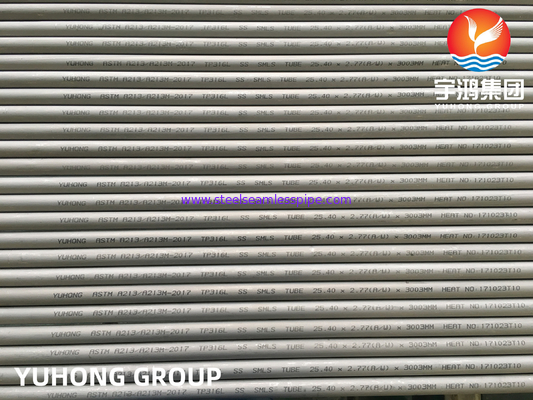
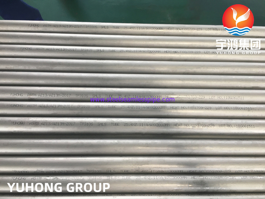
Stainless Steel Corrugated Tubes For Heat Exchangers TP304 / TP304L TP316 / TP316L 19.05X2.11MM
Quick Detail:
| General Low Fin Tubes Production Capacity |
Specifications of Low Fin Tubes('N' Fins) |
Finning Facility: 10 finning machines;
Daily capacity up to 3000 meters; |
Tube OD: 12.7 mm~25.4mm
Tube Length: 18 meters max.
Fin Height: 1.2 mm ~2.77mm
Fin Thickness: appr. 0.3mm
Fin Pitch: 30 FPI /28 FPI/ 26 FPI/ 36 FPI /43 FPI |
Description:
Manufacturing process: The fins are rolled out of outer wall of the plain tubes by a pass roller. Tubes and fins are in same piece tube. We call it “N” fin type.
Tube Materials:
ASTM A213 / A213M :Seamless Ferritic & Austenitic Alloy-Steel Boiler, Superheater, and Heat-Exchanger Tubes
ASTM A312/ A312M : Seamless, Welded, and Heavily Cold Worked Austenitic Stainless Steel Pipes
ASTM A269/ A269M :Seamless and Welded Austenitic Stainless Steel Tubing for General Service
Delivery Range of Low Fin Tubes
We can provide the integral low fin tubes with un-finned section gaps( 5mm Min.) in the middle of core tube OR bent with designed Bend Radius.
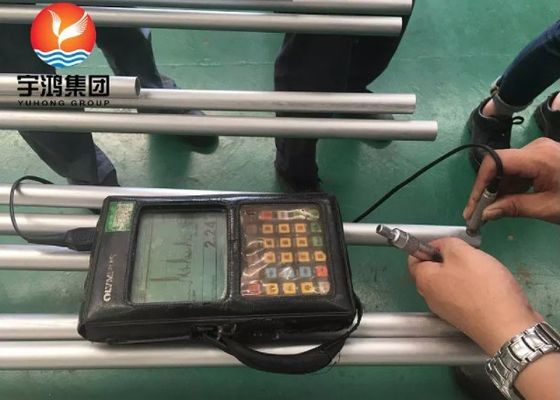
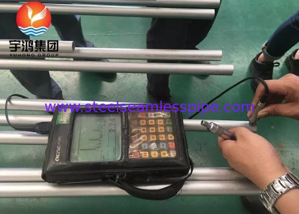
Quality Test:
The integral low fin tube quality is assured by hydrostatic or pneumatic tests, eddy current tests & MARCO tests in order to verify design specifications.
Acceptance Ceritia:
WOLVERINE / HPT / GEWA-K & GEWA-KS
Delivery Condition:
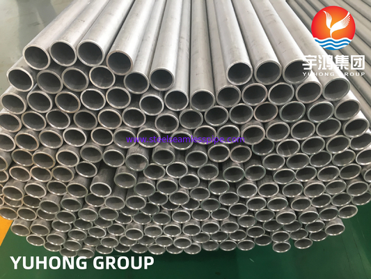
Tube ends are square cut, free burrs, internally dried and air blown clean, externally coated with varnish.
The desiccants are put into the each package for continental transportation.
Applications:
The Integral Low Finned Tubes find the preference in the following industrial sectors:
- Heating systems
- Ventilation systems
- Refrigeration and climate control systems
- Mechanical engineering
- Automotive manufacturing
- Chemicals and pertrochemical and power plant technology
Specifications:
Tube and fins consist of same tube and materials as carbon steel , low-alloy steels , stainless steel , brass , copper , cooper-nickel alloys , aluminum bronze , nickel alloys , titanium etc...
| Plain tube (mm) |
Finned section dimensions (mm) |
Ratio |
De |
| D×t |
Tp |
dd |
dr |
di |
η |
mm |
| 19×2 |
0.8 |
18.8 |
17 |
134 |
2.8 |
17.9 |
| 19×2 |
1 |
18.8 |
16.8 |
13.4 |
2.5 |
17.8 |
| 19×2 |
1.25 |
18.8 |
16.6 |
13 |
2.2 |
17.8 |
| 19×2 |
1.5 |
18.8 |
16.6 |
13 |
2 |
17.7 |
| 19×2 |
2 |
18.8 |
16.4 |
13 |
1.7 |
17.5 |
| 25×2.5 |
0.8 |
24.8 |
23 |
18.8 |
2.8 |
23.9 |
| 25×2.5 |
1 |
24.8 |
22.6 |
18.8 |
2.75 |
23.7 |
| 25×2.5 |
1.25 |
24.8 |
22.3 |
18 |
2.5 |
23.6 |
| 25×2.5 |
1.5 |
24.8 |
22.3 |
18 |
2.2 |
23.5 |
| 25×2.5 |
2 |
24.8 |
22 |
18 |
1.8 |
23.4 |
| 25×2.5 |
2.5 |
24.8 |
22 |
18 |
1.6 |
23.3 |
D------Outside diameter of plain end section
Dof----Diameter of top fins
Dr-----Root diameter of finned section
Di-----Inside diameter of finned section
T------Wall thickness of plain end section
Tp-----Fin pitch
De----Equivalent diameter of finned tube
L------Plain tube end length |
| Please email us for more information. |

ASTM A1012 : Standard Specification for Seamless and Welded Ferritic, Austenitic and Duplex Alloy Steel Condenser and Heat Exchanger Tubes With Integral Fins.
ASTM B891: Standard Specification for Seamless and Welded Titanium and Titanium Alloy Condenser and Heat Exchanger Tubes with Enhanced Surface for Improved Heat Transfer.
ASTM B924:Standard Specification for Seamless and Welded Nickel Alloy Condenser and Heat Exchanger Tubes With Integral Fins.

 Your message must be between 20-3,000 characters!