Yuhong Holding Group Co.,LTD
 |
| Place of Origin: | China |
| Brand Name: | YUHONG |
| Certification: | ISO9001:2015; ISO14001:2015; ISO45001:2018; PED 2014/68/EU; WPS/PQR/WPQ; ISO 3834 |
| Model Number: | N/A |
| Minimum Order Quantity: | 500kgs |
|---|---|
| Price: | To be discussed |
| Packaging Details: | Iron frame wooden case |
| Delivery Time: | 50-120 days |
| Payment Terms: | L/C,T/T |
| Supply Ability: | 5000 meters/day |
| Product: | Embedded Fin Tube | Material: | ASME SA179 |
|---|---|---|---|
| Application: | Air-Cooled Condensers | Package: | Iron Frame Wooden Case |
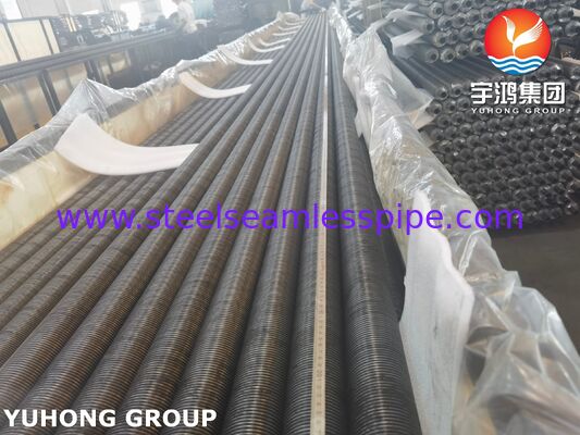
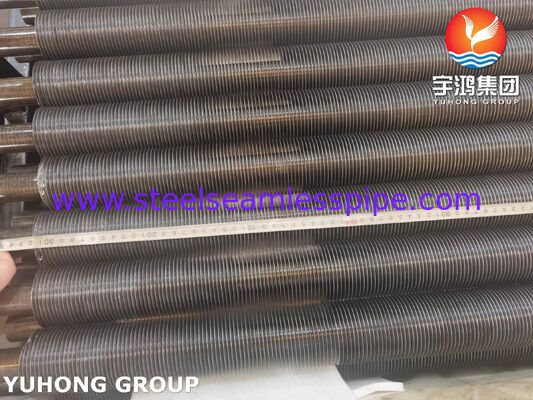
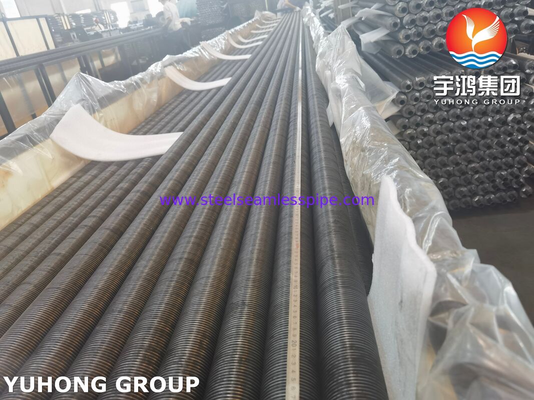
Embedded Finned Tubes for Air-Cooled Condensers (ACC) are engineered heat-transfer tubes designed to improve air-side heat-transfer performance in air-cooled condenser systems. Manufactured with a seamless ASME SA179 low-carbon steel base tube and an embedded helical fin construction, these tubes provide a large external heat-transfer surface while maintaining a reliable thermal path between the tube wall and fin.
ASME SA179 is the ASME-code counterpart of ASTM A179 and covers seamless, cold-drawn, low-carbon steel tubes intended for heat exchangers, condensers, and similar heat-transfer equipment. The specification covers tube outside diameters from 1/8 to 3 in. (3.2–76.2 mm).
For ACC applications, the fin is mechanically embedded into a precisely formed helical groove in the tube surface. The groove is produced in the base tube, the fin strip is inserted into the groove, and the tube is subsequently rolled to secure the fin. This construction creates a stable fin-to-tube connection and provides substantially greater external surface area than a bare tube.
Our SA179 embedded fin tubes can be manufactured according to project-specific requirements for tube diameter, wall thickness, fin material, fin height, fin pitch, fin thickness, tube length, fin density, and surface treatment.
Air-cooled condensers reject heat from steam or process vapor to atmospheric air without requiring a large quantity of cooling water. Because air has a considerably lower heat-transfer coefficient than water, the air-side surface area is particularly important.
Embedded fin tubes address this limitation by increasing the external surface area available for heat exchange.
The main advantages include:
For ACC designers, the fin geometry can be optimized according to air velocity, pressure drop, ambient temperature, heat duty, bundle configuration, and allowable fan power.
A typical embedded fin tube consists of:
1. Base Tube
Seamless, cold-drawn ASME SA179 low-carbon steel tube.
2. Helical Groove
A continuous groove is mechanically formed around the outside surface of the tube.
3. Fin Strip
A metallic fin strip—commonly aluminum or another application-selected material—is inserted into the groove.
4. Mechanical Embedding
The tube is rolled after fin insertion to firmly lock the fin into the tube wall.
5. Finished Finned Tube
The resulting assembly provides an enlarged external heat-transfer surface while retaining a continuous metallic heat-transfer path between the tube and fin.
The embedded-fin configuration is particularly useful where the fin must remain mechanically stable under continuous airflow, vibration, thermal cycling, and repeated operating conditions.
| Item | Typical Specification |
|---|---|
| Product | Embedded Finned Tube |
| Application | Air-Cooled Condenser (ACC) |
| Base Tube Material | ASME SA179 / ASTM A179 |
| Base Tube Type | Seamless, cold drawn |
| Base Tube OD | Approx. 12.7–76.2 mm; other sizes on request |
| Tube Wall Thickness | Approx. 1.5–5.0 mm; project dependent |
| Tube Length | 3,000–18,000 mm typical; longer lengths on request |
| Fin Type | Embedded / mechanically grooved helical fin |
| Fin Material | Aluminum alloy or other specified material |
| Fin Height | Approx. 6–25 mm |
| Fin Thickness | Approx. 0.2–0.8 mm |
| Fin Pitch | Approx. 1.5–8.0 mm |
| Fin Density | Approximately 125–670 fins/m, depending on design |
| Tube Ends | Plain, beveled, or project specified |
| Surface Finish | Mill finish, cleaned, coated or specified finish |
| Inspection | Dimensional, visual, material, mechanical and pressure/NDT testing as applicable |
| Standard | ASME SA179/SA179M; ASTM A179/A179M base tube requirements |
Note: The above fin dimensions represent common engineering ranges rather than mandatory values in SA179. The final tube and fin geometry should be established from the ACC thermal and mechanical design.
ASTM A179 itself specifies the base tube, rather than the complete embedded-fin geometry. Therefore, fin height, pitch, thickness, embedding depth and fin material are normally established by the purchaser's engineering specification or fin-tube manufacturer's design. ASTM identifies A179 as a seamless cold-drawn low-carbon steel tube specification for heat exchangers and condensers.
ASME SA179 is intended for seamless cold-drawn low-carbon steel heat-exchanger and condenser tubes. The tube is manufactured by the seamless process followed by cold drawing, with heat treatment after the final cold-drawing operation.
The low-carbon composition provides good ductility and forming characteristics, which are important when the tube surface is grooved and mechanically assembled with the fin.
| Element | Requirement, wt.% |
|---|---|
| Carbon (C) | 0.06–0.18 |
| Manganese (Mn) | 0.27–0.63 |
| Phosphorus (P), max. | 0.035 |
| Sulfur (S), max. | 0.035 |
These limits correspond to the A179/A179M material requirements; SA179 is the related ASME designation for code applications.
Typical minimum mechanical requirements for SA179/A179 base tubes are:
| Property | Requirement |
|---|---|
| Tensile Strength | ≥ 325 MPa (47,000 psi) |
| Yield Strength | ≥ 180 MPa (26,000 psi) |
| Elongation in 50 mm | ≥ 35% |
| Hardness | ≤ 72 HRB |
The relatively high elongation requirement is useful for a tube that undergoes cold-drawing and subsequent mechanical processing during fin-tube manufacture.
Our typical manufacturing sequence for SA179 embedded fin tubes includes:
SA179 seamless low-carbon steel tube is produced and supplied in accordance with the applicable material specification.
The base tube is cold drawn to achieve the required dimensions and surface condition. A179 requires heat treatment following the final cold-draw pass.
The base tubes are inspected for dimensional accuracy, surface condition, material identification and applicable mechanical requirements.
A controlled helical groove is formed on the tube outside diameter.
The fin strip is accurately positioned inside the helical groove.
Mechanical rolling forces the tube material around the fin root, securing the fin within the groove.
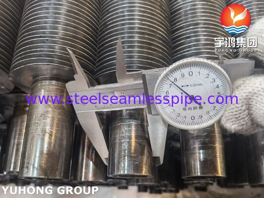
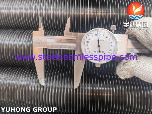
Fin height, pitch, thickness, embedding condition and overall diameter are checked against the approved drawing.
Finished tubes are inspected for dimensional accuracy, fin attachment, surface condition, straightness and other project-specific requirements.
Quality control can include both base-tube testing required by the material specification and additional inspection of the finished finned tube.
Heat analysis and, where required by the purchase order, product analysis are performed to verify compliance with the specified SA179 chemistry.
A179 provides for product analysis when requested by the purchase order, including sampling provisions based on tube quantity or heat identification.
Tensile testing verifies:
The results are compared with the specified SA179 mechanical requirements.
Rockwell hardness testing can be performed to verify that the base tube remains within the specified hardness range.
A flattening test evaluates the tube's ductility and ability to withstand deformation without unacceptable cracking. A179 includes flattening testing among its specified mechanical tests.
The flaring test evaluates tube ductility and resistance to cracking during controlled expansion.
Where specified as an alternative to the flaring test, flange testing can be performed according to the applicable requirements.
Hydrostatic testing is used to verify pressure integrity and identify leakage through the tube wall.
Depending on the purchase specification, nondestructive examination such as an eddy-current test or other applicable NDT can be incorporated.
ASTM A179 and its associated general requirements reference testing such as hardness, flattening, flaring, flange and hydrostatic testing; A450/A450 also includes provisions for nondestructive testing.
Finished embedded fin tubes can be inspected for:
The finished product is visually inspected for:
The A179 specification also requires the finished base tubes to be free from scale, although slight oxidation is not considered scale.
The fin greatly increases the external heat-transfer surface available to the cooling air.
The embedded construction mechanically locks the fin into the tube, helping maintain contact during thermal cycling and vibration.
The configuration can be manufactured in long tube lengths and customized for large condenser assemblies.
The seamless SA179 base tube provides a smooth internal passage suitable for condenser service.
Fin height, pitch and material can be adjusted according to the thermal design and allowable air-side pressure drop.
SA179 provides a practical low-carbon steel option for condenser and heat-exchanger tube applications.
ASME SA179 embedded finned tubes are suitable for a variety of air-cooled heat-transfer systems, including:
For power-generation ACC systems, the finned tube is normally installed in large tube bundles. Hot exhaust steam or condensate-side fluid transfers heat through the tube wall to the fin, while fans force or induce atmospheric air across the external fin surface.
We can manufacture embedded finned tubes according to customer drawings, thermal calculations or project specifications.
Typical customizable parameters include:
Inspection documentation can be supplied according to the purchase order, including material certificates, dimensional inspection records, mechanical test results and applicable NDT/pressure-test records.
Embedded Finned Tubes for Air-Cooled Condensers (ACC), ASME SA179, combine seamless cold-drawn low-carbon steel tubes with mechanically embedded helical fins to provide increased air-side heat-transfer area and reliable fin-to-tube contact. They are designed for air-cooled condenser and heat-exchanger applications where efficient heat rejection, dimensional consistency and durable fin attachment are required.
The SA179 base tube conforms to the requirements for seamless cold-drawn low-carbon steel heat-exchanger and condenser tubes, while the finished fin geometry can be engineered to meet the thermal, mechanical and installation requirements of the ACC system.
Contact Person: Nacy
Tel: +8619965117039
Fax: 0086-574-88017980