Yuhong Holding Group Co.,LTD
 |
| Place of Origin: | China |
| Brand Name: | YUHONG |
| Certification: | ISO9001:2015; ISO14001:2015; ISO45001:2018; PED 2014/68/EU; WPS/PQR/WPQ; ISO 3834 |
| Model Number: | N/A |
| Minimum Order Quantity: | 500kgs |
|---|---|
| Price: | To be discussed |
| Packaging Details: | Plywood case or Iron frame wooden case |
| Delivery Time: | 50-120 days |
| Payment Terms: | L/C,T/T |
| Supply Ability: | 5000 meters/day |
| Product: | Wound Fin Tube | Material: | ASME SA179 |
|---|---|---|---|
| Application: | Air-Cooled Heat Exchangers (ACHEs) | Package: | Plywood Case Or Iron Frame Wooden Case |
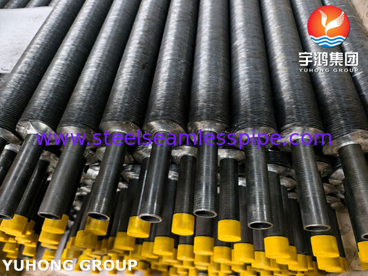
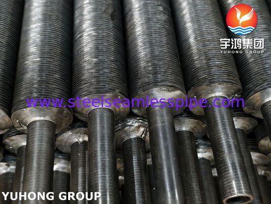
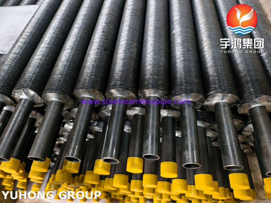
Wound-fin tubes for air-cooled heat exchangers are designed to improve heat-transfer efficiency by increasing the external surface area available for heat exchange between the tube-side fluid and surrounding air. Manufactured with a seamless cold-drawn carbon steel base tube to ASME SA179 / ASTM A179, these tubes are suitable for a wide range of industrial cooling applications where reliable heat transfer, dimensional consistency, and economical operation are important.
During production, metal fins are helically wound around the base tube. Depending on the operating environment and engineering requirements, the fin design may incorporate L-foot, knurled L-foot, or other specified attachment configurations. The finished tubes can be supplied in customized lengths and fin geometries to meet the requirements of air-cooled heat exchangers, fin-fan coolers, and industrial process cooling systems.
ASME SA179 is the base-tube material specification; it does not, by itself, define the fin material, fin attachment method, or complete wound-fin tube dimensions. These details should be specified separately to ensure the finished product meets the intended operating conditions.
Enhanced heat-transfer area: Helically wound fins increase the air-side surface area, supporting more efficient heat exchange in compact equipment.
Reliable base-tube material: SA179 low-carbon steel tubing offers good thermal conductivity and is suitable for many low- and moderate-temperature heat-exchanger duties.
Flexible fin configurations: Fin height, thickness, pitch, material, and attachment style can be selected according to thermal performance and operating requirements.
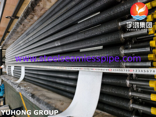
Customized manufacturing: Tube diameter, wall thickness, overall length, and finned length can be tailored to customer drawings.
Industrial versatility: Suitable for process-fluid cooling, lubricant oil cooling, gas cooling, and other compatible heat-transfer services.
Quality-focused production: Dimensional inspection, material verification, pressure-related testing, and applicable non-destructive examinations can be incorporated into the inspection plan.
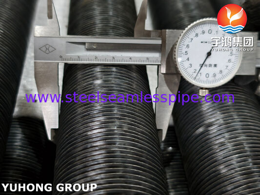
The following dimensions are representative manufacturing ranges for wound-fin tubes used in air-cooled heat exchangers. Final dimensions depend on the thermal design, fan capacity, operating temperature, and customer drawings.
|
Parameter |
Typical specification |
|---|---|
|
Base tube material |
ASME SA179 / ASTM A179 |
|
Base tube manufacturing |
Seamless, cold-drawn, heat-treated |
|
Base tube outside diameter |
12.7–76.2 mm |
|
Base tube wall thickness |
1.2–4.5 mm |
|
Overall tube length |
1,000–18,000 mm |
|
Fin material |
Aluminum alloy, carbon steel, or other specified material |
|
Fin type |
Helically wound; L-foot, knurled L-foot, or specified attachment |
|
Fin height |
10–25 mm |
|
Fin thickness |
0.3–0.5 mm for common aluminum-fin designs |
|
Fin pitch |
Approximately 2.1–5.0 mm |
|
Surface finish |
As manufactured, coated, or otherwise specified |
|
End finish |
Plain ends, bevelled ends, or customized to drawings |
Note: The dimensions above are typical commercial options, not mandatory limits established by SA179. The base-tube standard covers outside diameters from 3.2 to 76.2 mm; fin geometry and finished-tube dimensions must be agreed upon separately.
For accurate quotations and manufacturing, customers should specify:
Base tube outside diameter and wall thickness.
Total tube length and effective finned length.
Fin material, thickness, height, and pitch.
Fin attachment type and required contact or bonding quality.
Operating temperature, pressure, and process-fluid conditions.
Required inspection level, documentation, and applicable code edition.
ASME SA179 is a low-carbon steel specification intended for seamless, cold-drawn heat-exchanger and condenser tubes. Its chemical composition is controlled to provide suitable formability, strength, and manufacturing consistency.
|
Element |
Composition by weight (%) |
|---|---|
|
Carbon (C) |
0.06–0.18 |
|
Manganese (Mn) |
0.27–0.63 |
|
Phosphorus (P) |
0.035 max. |
|
Sulfur (S) |
0.035 max. |
These limits apply to the base tube, not necessarily to the fin strip. Fin chemistry depends on the selected fin material and should be specified separately.
The following are the commonly specified minimum mechanical requirements for SA179 base tubing. Final acceptance should follow the applicable edition of ASME Section II, Part A, and the purchase order.
|
Property |
Requirement |
|---|---|
|
Tensile strength |
325 MPa minimum |
|
Yield strength |
180 MPa minimum |
|
Elongation in 50.8 mm (2 in.) |
35% minimum |
|
Hardness |
72 HRB maximum, or equivalent specified limit |
To ensure consistent quality and reliable operation, wound-fin tubes can be inspected at both the base-tube manufacturing stage and the completed finned-tube stage.
1. Dimensional inspection
Measure base-tube outside diameter, wall thickness, straightness, overall length, fin height, fin pitch, fin thickness, and finned length. Verify tolerances against the approved drawing and purchase specification.
2. Chemical composition analysis
Verify the base-tube chemistry through heat analysis and, where required, product analysis. Check fin-strip material certification separately.
3. Mechanical testing
Tensile, hardness, flattening, and flaring tests are used as applicable to verify compliance with SA179 and the referenced general requirements. A flange test may be used where permitted and specified.
4. Hydrostatic or specified electrical testing
The base tube is subjected to the test required by the applicable specification. Testing of the completed finned assembly should follow the agreed inspection plan and equipment design requirements.
5. Fin attachment and visual inspection
Check fin spacing, winding uniformity, fin damage, attachment integrity, tube-end condition, surface defects, and overall workmanship. Additional bond or pull-off tests may be agreed upon for the specified fin design.
The SA179 base-tube specification includes chemical analysis, mechanical and dimensional requirements, and hydrostatic or electrical testing provisions. Additional inspection of fin attachment and finished geometry should be defined separately.
Depending on the project requirements, documentation can include:
Material Test Certificate (EN 10204 3.1, where contractually agreed).
Chemical composition and mechanical test reports.
Dimensional inspection records.
Base-tube hydrostatic or electrical test records.
Fin-material certificates and finished-product inspection reports.
Traceability records and packing inspection reports.
Air-Cooled Heat Exchangers (ACHEs)
The primary application. Wound-fin tubes increase the air-side heat-transfer area, allowing process fluids to be cooled by forced or natural air circulation in suitable equipment.
Oil and Gas Processing
Used in compatible fin-fan coolers for process-fluid cooling, lubricant oil cooling, and other services where the base-tube material meets the design requirements.
Petrochemical and Chemical Plants
Suitable for selected cooling duties in process equipment where enhanced air-side heat transfer helps reduce equipment footprint.
Compressor and Machinery Cooling
Applied in compatible oil coolers and auxiliary heat exchangers to dissipate heat from lubricating oils and other process fluids.
SA179 is a low-carbon steel tube grade, so the suitability of the finished product depends on operating temperature, pressure, corrosion exposure, and fin material. For corrosive environments or higher-temperature service, the material selection should be verified by the equipment designer.
Our wound-fin tubes are manufactured to customer specifications, with attention to base-tube quality, fin attachment consistency, and finished dimensions.
Specification compliance: Base tubes manufactured to the agreed ASME SA179 requirements.
Custom fin geometry: Fin pitch, height, thickness, and attachment options tailored to project requirements.
Application-focused manufacturing: Tube configurations selected to suit the thermal and mechanical design.
Quality assurance: Material traceability and inspection documentation available according to contract requirements.
Flexible supply: Customized tube lengths, finned sections, end preparations, and packaging for industrial projects.
Contact Person: Nacy
Tel: +8619965117039
Fax: 0086-574-88017980